
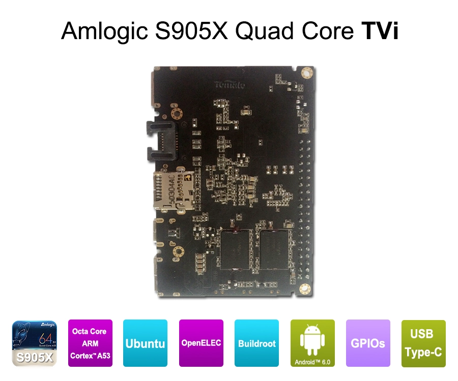
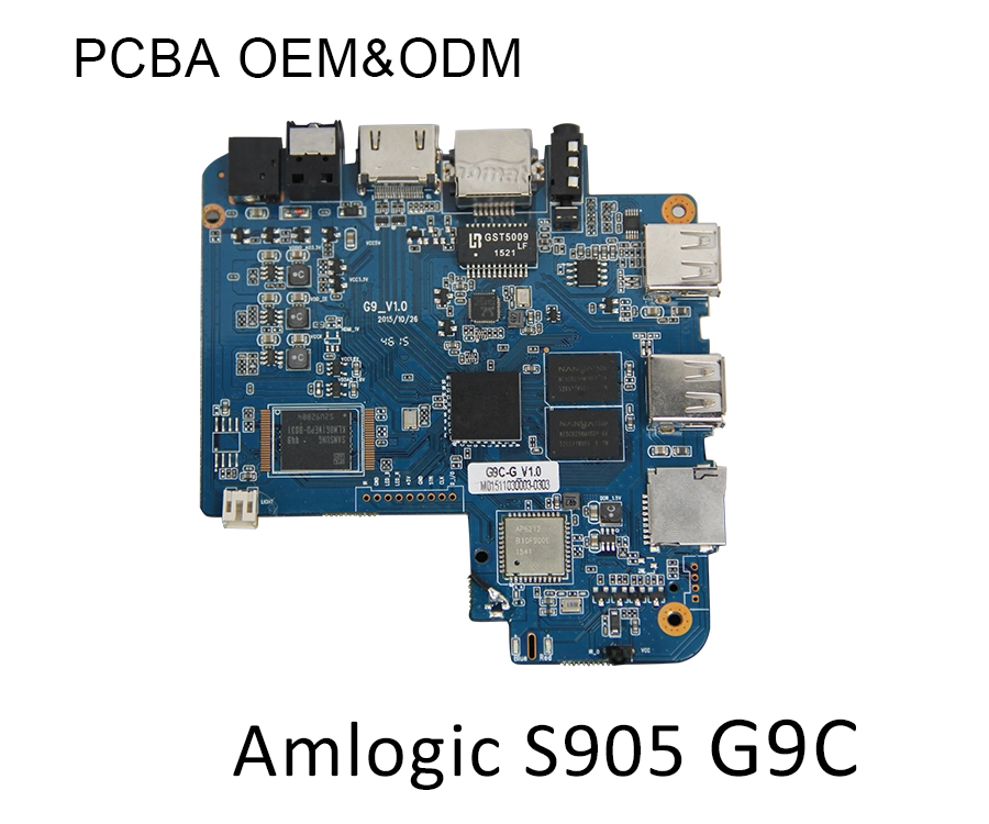
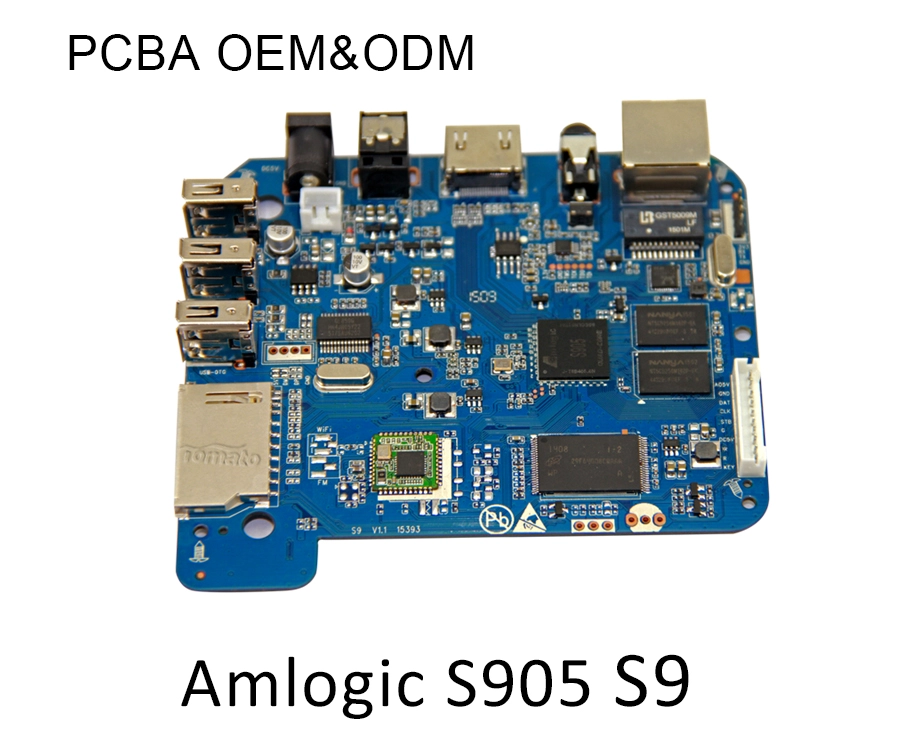
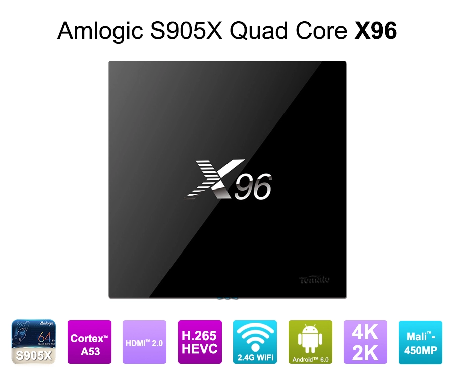
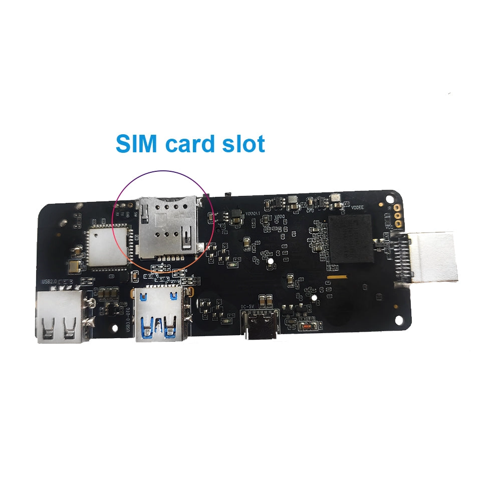
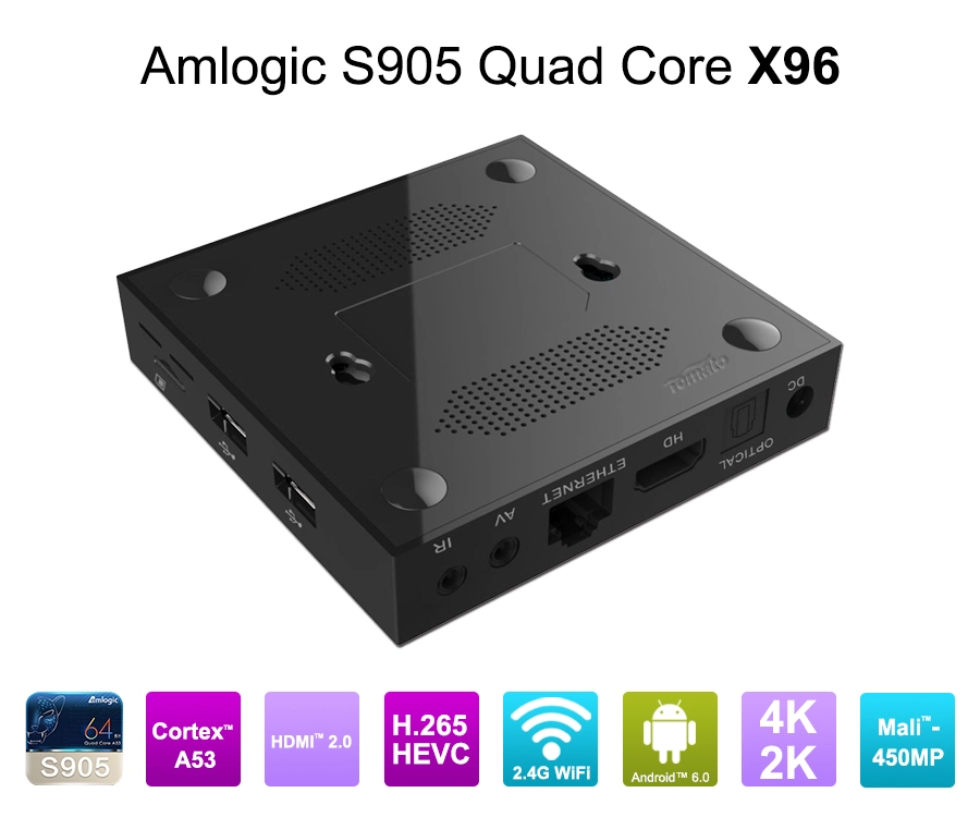
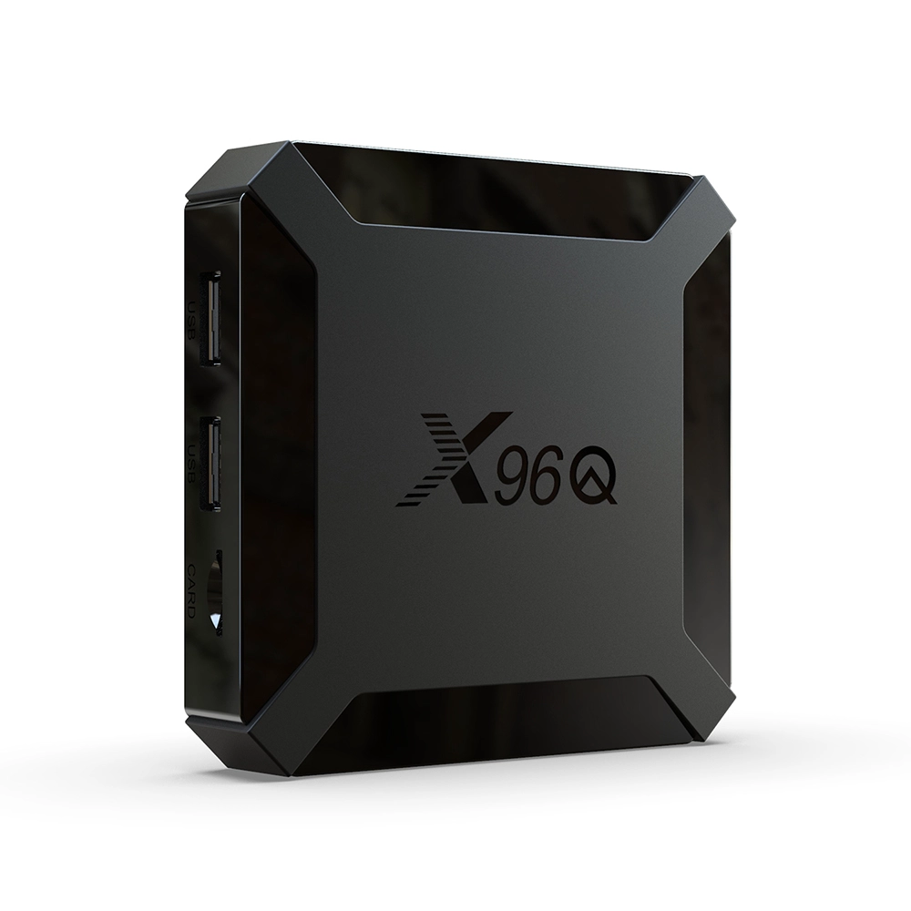
TV Box Circuit Design for Reliable 4K/8K HDR and HDMI IN/OUT
1. Why TV Box Circuit Design Determines 4K/8K Video Reliability
A modern TV Box may support 4K@60Hz or 8K video decoding at the SoC level, but that specification does not guarantee stable output through the HDMI interface.
The actual video pipeline involves several interconnected hardware components:
-
SoC video decoder and display processing engine.
-
DDR memory interface and high-speed data buses.
-
HDMI transmitter and associated signal conditioning circuits.
-
Power management ICs and voltage regulation.
-
PCB transmission lines and impedance-controlled routing.
-
HDMI connectors, ESD protection, and electromagnetic compatibility components.
A weakness in any of these areas can produce intermittent black screens, signal dropouts, HDR negotiation failures, audio synchronization problems, or unstable display output.
For B2B manufacturers, these failures are particularly expensive. A TV Box deployed across hundreds or thousands of hotel rooms, digital signage installations, IPTV networks, or commercial displays must maintain consistent performance under continuous operating conditions.
1.1 SoC Selection Must Match the Actual Video Pipeline
The first decision is selecting a processor that supports the required resolution, frame rate, codec, HDR formats, and interface configuration.
Different SoC platforms provide different combinations of video decoding, display processing, memory bandwidth, and HDMI capabilities.
|
Engineering requirement |
Design consideration |
|---|---|
|
4K@60Hz |
Hardware decoding, display engine, HDMI output bandwidth |
|
8K@60Hz |
SoC-specific codec support, memory bandwidth, interface capability |
|
HDR10 / HDR10+ |
HDR metadata processing and display compatibility |
|
Dolby Vision |
Supported SoC, licensing, firmware and display pipeline |
|
AV1 decoding |
Dedicated hardware decoding capability |
|
HDMI IN |
Capture interface, video processing and input switching |
|
Multi-display output |
Display engine resources and interface configuration |
One important distinction is that codec decoding capability and HDMI output capability are separate specifications.
For example, a processor may decode 8K video internally but only support a particular HDMI output configuration. The final design must follow the SoC manufacturer's documented interface capabilities rather than relying on the maximum resolution listed in a marketing specification.
1.2 PCB Layout and Signal Integrity
High-resolution HDMI transmission requires careful PCB engineering.
The HDMI differential pairs must maintain controlled impedance, appropriate differential spacing, and consistent routing geometry. Excessive trace length, unnecessary vias, impedance discontinuities, and poor return-path design can introduce reflections and signal degradation.
A reliable TV Box PCBA design should address:
-
Controlled-impedance differential routing.
-
Matched differential-pair lengths within the applicable design tolerance.
-
Continuous reference planes beneath high-speed signals.
-
Appropriate separation between noisy power circuits and sensitive signal paths.
-
Minimized connector-to-SoC transmission distance.
-
Proper ESD protection and high-speed signal integrity.
For HDMI 2.1 FRL applications, routing requirements become more demanding because of the higher data rates involved.
The design team should also consider connector quality, PCB material properties, stack-up configuration, via structures, and signal conditioning components during the initial motherboard design stage.
Engineering principle: A TV Box should be designed around the complete electrical transmission path, not simply the HDMI connector and the processor specification.
2. HDMI IN/OUT Circuit Architecture: From Video Output to Signal Capture
HDMI OUT and HDMI IN serve different engineering purposes. HDMI OUT transmits processed video and audio from the TV Box to an external display. HDMI IN receives an external HDMI source and routes its signal into the device for processing, capture, or display.
Adding HDMI IN is not simply a matter of installing a second HDMI connector. It changes the PCBA architecture, interface selection, firmware configuration, and system validation requirements.
2.1 HDMI OUT: Stable Video and Audio Transmission
A typical HDMI OUT circuit includes:
-
SoC display output interface.
-
HDMI transmitter or integrated HDMI PHY.
-
High-speed differential signal routing.
-
ESD protection components.
-
HDMI connector and supporting control circuits.
The HDMI interface must also manage DDC communication, EDID reading, Hot Plug Detect (HPD), and HDCP authentication.
When a TV Box connects to a television or commercial display, the source and sink negotiate supported video formats. This process determines the available resolution, refresh rate, color depth, and HDR capabilities.
Poor EDID handling or unstable HPD detection can cause problems such as:
-
No signal after powering on the display.
-
Incorrect resolution selection.
-
Intermittent black screens when switching video modes.
-
HDR output reverting to SDR.
-
Audio disappearing after HDMI reconnection.
For commercial deployments, the firmware should include reliable HDMI hot-plug handling, display-mode detection, and recovery logic.
2.2 HDMI IN: Additional Hardware for Video Capture
HDMI IN requires a different signal-processing path.
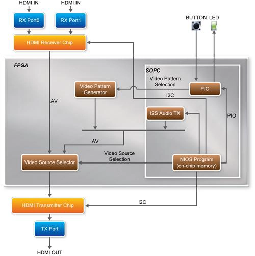
A typical architecture may include:
-
HDMI input connector.
-
HDMI receiver or video capture IC.
-
HDCP-compliant input handling where applicable.
-
Video processing or capture interface.
-
SoC input processing pipeline.
-
DDR memory buffering.
-
HDMI output transmitter.
-
Audio capture and synchronization circuits.
The actual architecture depends on whether the project requires direct pass-through, video capture, picture-in-picture, live preview, or content analysis.
For example, a commercial TV Box used in an interactive display installation may receive an external video source through HDMI IN, process the input, and display it through HDMI OUT.
However, engineers must distinguish between an HDMI receiver and a video capture interface. An HDMI receiver alone does not guarantee that the SoC can ingest and process the received video. The receiver's output interface must match the available SoC input resources, such as MIPI CSI-2, parallel video, or another supported interface.
This is one reason why HDMI IN projects require early hardware architecture planning rather than late-stage connector modification.
2.3 HDMI IN/OUT: Key Design Differences
|
Design factor |
HDMI OUT |
HDMI IN |
|---|---|---|
|
Primary function |
Video transmission |
Video reception |
|
Main hardware |
HDMI transmitter / PHY |
HDMI receiver / capture IC |
|
EDID management |
Display capability detection |
Source capability negotiation |
|
HDCP |
Source authentication and encryption |
Protected-content authentication and handling |
|
Data processing |
Display pipeline |
Capture and input processing |
|
Main challenges |
Signal integrity and display compatibility |
Input compatibility, capture bandwidth and latency |
2.4 HDCP and Content Protection
HDCP (High-bandwidth Digital Content Protection) is an important consideration in commercial HDMI product development.
A TV Box with HDMI IN must not assume that every external HDMI signal can be captured or processed. Protected content is subject to HDCP authentication, licensing, and compliance requirements.
The design team must determine whether the intended application requires:
-
Standard HDMI input without protected-content capture.
-
Authorized HDCP authentication and repeater functionality.
-
HDMI pass-through with compliant content protection.
-
Capture of unprotected external video sources.
HDCP support is not a software switch that can be added to any HDMI receiver. It depends on licensed hardware, implementation, certification, and the applicable content-protection requirements.
For OEM/ODM projects, the intended signal path should be defined before selecting the HDMI receiver, transmitter, and SoC.
3. Power Integrity, Thermal Management, and Firmware Optimization
A TV Box can pass initial laboratory testing and still experience failures after several hours of continuous operation. This often happens because engineering validation focuses on basic video playback rather than the combined electrical, thermal, and software behavior of the complete system.
3.1 Power Management for High-Speed Interfaces
The SoC, DDR memory, HDMI interface, Wi-Fi module, and peripheral circuits have different power requirements.
An appropriate power architecture should consider:
-
Dedicated voltage rails for the SoC and memory.
-
Low-noise power delivery for sensitive analog and PHY circuits.
-
Adequate transient response during peak processing loads.
-
Proper decoupling capacitor placement.
-
Power sequencing based on SoC requirements.
-
Ground-plane continuity and return-current paths.
Voltage instability can cause HDMI link retraining, memory errors, processor instability, or unexpected system resets.
For a TV Box supporting 4K HDR playback, power consumption can increase when the processor, GPU, video decoder, wireless module, and display engine operate simultaneously.
The power design must therefore be validated under realistic combined workloads rather than idle or light-load conditions.
3.2 Thermal Design for Continuous Commercial Operation
Thermal management is particularly important for industrial TV Box and digital signage applications.
An enclosed device installed behind a commercial display may have limited airflow. When the SoC operates at high utilization, excessive temperature can trigger thermal throttling and reduce sustained processing performance.
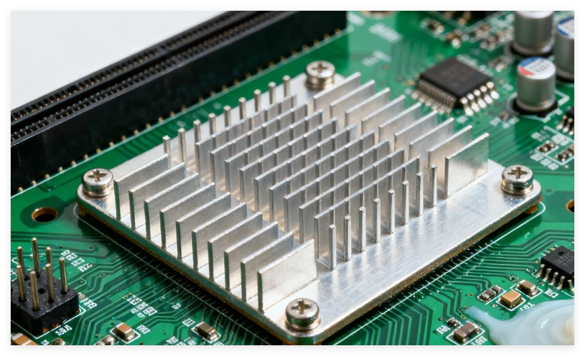
A suitable cooling strategy may combine:
-
Aluminum heatsinks.
-
Thermal pads with appropriate conductivity and compression.
-
Optimized SoC and memory component placement.
-
PCB copper area for heat spreading.
-
Ventilation and enclosure airflow optimization.
-
Active cooling where the application requires it.
SZTomato supports specialized cooling solutions for industrial-use TV Box projects, with thermal design adapted to enclosure dimensions, operating environments, and continuous-duty requirements.
The objective is not simply to achieve a low temperature during a short test. It is to maintain stable processing performance throughout the intended operating cycle.
3.3 Linux and Android Kernel Optimization
Hardware design and firmware engineering must be developed together.
Even when the HDMI circuit is electrically correct, software-level problems can affect video output and input compatibility.
A professional TV Box firmware solution should consider:
Android/Linux kernel and device drivers
-
HDMI PHY initialization and configuration.
-
Display subsystem and framebuffer management.
-
HDMI hot-plug event handling.
-
EDID parsing and display-mode selection.
-
Video capture driver integration for HDMI IN.
-
Audio routing and synchronization.
Android framework and multimedia stack
-
Hardware video decoding.
-
HDR metadata handling.
-
SurfaceFlinger and display composition.
-
Audio-video synchronization.
-
Resolution and refresh-rate switching.
-
System-level HDMI input management.
OTA update and long-term maintenance
An OTA update system should support controlled firmware distribution, version management, recovery mechanisms, and rollback strategies where the platform permits them.
For commercial deployments, this is particularly important because updating devices individually is costly. A reliable firmware architecture allows operators to maintain consistent configurations across distributed installations.
SZTomato integrates custom UI/UX firmware, SDK/API integration, and hardware-level modifications to align the TV Box with the customer's application requirements.
3.4 HDMI Compatibility Testing Must Cover Real Operating Conditions
A reliable validation process should include more than checking whether an image appears on the display.
|
Test category |
Recommended validation |
|---|---|
|
Resolution |
Supported 4K/8K output modes |
|
HDR |
HDR10, HDR10+ or other licensed formats where supported |
|
HDMI negotiation |
EDID, HPD and mode switching |
|
HDCP |
Authentication and compliant signal handling |
|
Audio |
PCM, supported bitstream formats and synchronization |
|
Thermal |
Sustained operation under high processing loads |
|
Power |
Voltage stability during peak workloads |
|
Compatibility |
Multiple display brands, cables and AV receivers |
|
HDMI IN |
Capture, input switching and latency where applicable |
|
OTA |
Firmware upgrade, recovery and rollback behavior |
The test matrix should be based on the actual product requirements and supported SoC capabilities. Not every TV Box needs 8K output, HDMI IN, or every HDR format. Adding unsupported or unnecessary features increases development cost without necessarily improving the commercial product.
4. TV Box Circuit Design Trends: HDMI 2.1/2.2, 8K HDR, and OEM/ODM Customization
The next generation of TV Box products will be shaped by higher video bandwidth, more demanding commercial applications, and closer integration between hardware and software.
For manufacturers, the challenge is not simply adopting a newer HDMI specification. It is selecting an architecture that meets the actual performance requirements without creating unnecessary BOM costs or long-term compatibility problems.
4.1 HDMI 2.1 and HDMI 2.2: Plan for the Correct Bandwidth
HDMI 2.1 introduced bandwidth up to 48Gbps using Fixed Rate Link (FRL), supporting applications including 8K@60Hz and 4K@120Hz under supported configurations.
The HDMI 2.2 specification, released in June 2025, raises the maximum bandwidth to 96Gbps and introduces next-generation FRL technology. It expands support for higher resolutions, refresh rates, and advanced color formats.
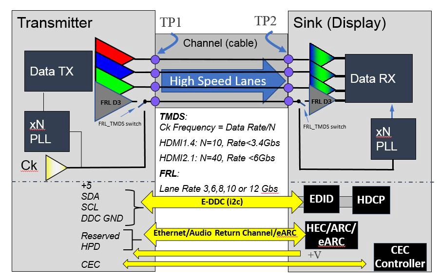
For TV Box manufacturers, these developments have several implications:
-
Higher-speed interfaces require more demanding PCB transmission-line design.
-
HDMI transmitter and receiver selection must match the intended data rate.
-
Signal integrity and EMI testing become increasingly important.
-
Connector and cable capabilities must match the target operating mode.
-
SoC support must be confirmed before defining product specifications.
One important engineering point: a firmware update cannot transform an HDMI 2.1 hardware implementation into a fully compliant HDMI 2.2 interface. Higher-bandwidth FRL capabilities depend on compatible silicon and physical interface architecture.
Therefore, manufacturers planning a long product lifecycle should consider interface scalability during the initial SoC and PCBA selection stages.
4.2 HDR Is a Complete Display Pipeline Requirement
HDR support is frequently used as a product selling point, but actual HDR performance depends on multiple components working together.
A complete HDR pipeline includes:
-
Hardware decoding of the source video.
-
Correct interpretation of HDR metadata.
-
Display processing and color-space conversion.
-
HDMI transmission with the required color depth and format.
-
EDID negotiation with the connected display.
-
Compatible display-side HDR processing.
Formats such as HDR10, HDR10+, and Dolby Vision have different implementation and licensing requirements.
A TV Box that decodes HDR content but outputs an incorrect color format or fails to preserve metadata may produce washed-out colors, incorrect brightness, or SDR output.
For OEM projects, the supported HDR formats should be confirmed at the SoC, firmware, HDMI interface, and display compatibility levels.
4.3 Custom PCBA Design Is More Practical Than Forcing a Generic Reference Board
A standard reference design is useful for shortening development time, but it does not always meet the requirements of commercial applications.
Consider three common project scenarios:
|
Application |
Recommended engineering priorities |
|---|---|
|
IPTV and telecom operators |
Stable HDMI output, HDCP compliance, OTA management and customized middleware |
|
Digital signage integrators |
Continuous operation, thermal management, remote device management and custom interfaces |
|
Professional AV systems |
HDMI IN/OUT integration, signal switching, audio synchronization and low-latency processing |
A commercial TV Box may require additional USB ports, Ethernet interfaces, serial communication, GPIO, external storage, or specialized video input capabilities.
These requirements affect motherboard dimensions, component placement, power distribution, firmware drivers, and enclosure design.
SZTomato approaches these projects through coordinated hardware and software development:
-
PCBA hardware modification: Adapt circuit architecture, interface configuration, component selection, and motherboard layout to project specifications.
-
SDK/API integration: Connect the TV Box with IPTV platforms, CMS systems, third-party applications, and customer management systems.
-
Custom UI/UX firmware: Develop branded interfaces, customized startup behavior, application management, and system-level functions.
-
Industrial thermal solutions: Optimize heat dissipation for enclosed devices and continuous commercial operation.
-
Long-term firmware support: Support platform maintenance, OTA updates, driver integration, and application compatibility.
The advantage of this approach is that hardware and firmware decisions are made together. This reduces the risk of completing PCB development only to discover that the required interface or software functionality cannot be supported.
4.4 Engineering Validation Before Mass Production
Before approving a TV Box for mass production, B2B buyers should request evidence that the actual hardware configuration meets the project requirements.
A practical validation process includes:
-
Schematic and PCB design review.
-
Power integrity and thermal testing.
-
HDMI electrical and interoperability testing.
-
Supported resolution and HDR verification.
-
HDCP implementation and compliance verification.
-
Android/Linux driver and firmware validation.
-
EMC/EMI and ESD testing.
-
Pilot production and extended reliability testing.
For HDMI products, manufacturers should also verify applicable HDMI adopter obligations, licensing requirements, and Authorized Testing Center procedures. Product claims should accurately reflect the tested implementation rather than relying solely on chipset marketing specifications.
The most effective time to identify a circuit-design problem is during engineering validation, not after deployment in a customer's network.
Conclusion: Build a TV Box Around the Application, Not Just the Chipset
A reliable 4K/8K HDR TV Box requires coordinated engineering across SoC selection, PCBA layout, HDMI signal integrity, power management, thermal design, and firmware development.
HDMI IN/OUT integration introduces additional challenges involving video capture, signal routing, HDCP, audio synchronization, and software compatibility. These requirements make a generic reference design unsuitable for some professional applications.
For B2B procurement managers, telecom operators, brand owners, and system integrators, choosing a manufacturer should involve more than comparing processor models, memory configurations, and advertised video resolutions.
The manufacturer's ability to modify hardware, integrate interfaces, optimize firmware, and support the product throughout its lifecycle is equally important.
SZTomato – OEM/ODM TV Box Manufacturing and Engineering
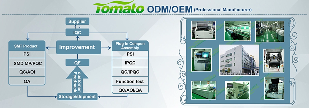
Established in 2011, SZTomato provides OEM/ODM manufacturing and engineering services for Android TV Box, Smart TV Box, IPTV Set-Top Box, Streaming Media Player, and commercial multimedia hardware projects.
Our engineering capabilities cover:
-
Custom PCBA design and hardware modification.
-
HDMI IN/OUT interface integration.
-
4K/8K video processing architecture.
-
Android/Linux firmware customization.
-
SDK/API integration and application development.
-
Custom UI/UX and OTA update systems.
-
Industrial thermal management solutions.
-
Product validation and mass-production support.
Whether your project requires a customized 4K HDR TV Box, an 8K multimedia platform, or an HDMI IN/OUT solution for professional AV applications, SZTomato can help develop a hardware and firmware architecture aligned with your commercial requirements.
Planning an OEM/ODM TV Box project?
Visit SZTomato to discuss your requirements with our engineering team. Share your target SoC, video resolution, HDMI interface configuration, operating system, and application scenario to start a technical evaluation.
