

How do I connect a TV Box?
Commercial TV Box Deployment: Engineering Stable AV and Network Architecture
Hardware deployment failures at the integration phase directly impact project ROI. In multi-screen commercial rollouts, a simple connectivity failure rarely stems from a faulty cable; it is typically caused by unmanaged Extended Display Identification Data (EDID) mismatches, unstable network provisioning, or voltage drops across long cable runs.
When deploying a commercial TV Box fleet, integration teams must move past residential plug-and-play assumptions. Achieving a reliable, continuous installation requires configuring precise hardware handshakes, establishing stable data pipelines, and implementing automated device provisioning at the firmware level.
1. AV Interface Engineering: Resolving the HDMI EDID Handshake
The primary bottleneck when connecting a TV Box to commercial displays or matrix switchers is the HDMI handshake. EDID is the signaling protocol used by a display to communicate its resolution, refresh rate, and color space capabilities to the source media player.
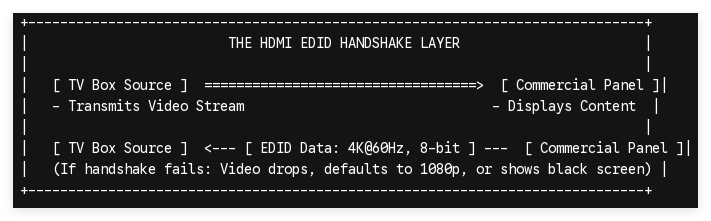
In complex systems involving long HDMI extensions or distribution amplifiers, this handshake often fails, resulting in black screens, interlacing artifacts, or downscaled resolutions. To establish a stable connection:
-
Force Resolution at the Kernel Level: Avoid using auto-negotiation settings in the firmware. Configure the hardware to output a fixed video profile (such as 4K at 60Hz with 8-bit color depth) that matches the target display specifications.
-
Deploy Active Signal Conversion: When distance requires running cable over 15 meters, passive copper cables experience high-frequency signal loss. Use active optical HDMI cables or HDBaseT transmitters to maintain line equalization and metadata transmission.
-
Manage HDCP Compliance: High-bandwidth Digital Content Protection (HDCP) keys can delay source switching. For non-protected commercial content networks, utilizing custom firmware that allows disabling HDCP handshaking prevents display sync delays.
2. Power and Data Distribution: Transitioning to PoE Architecture
Relying on standard DC wall adapters introduces multiple failure points into enterprise installations. In crowded server racks or high-altitude ceiling mounts, separate power supplies complicate cable management and increase thermal loads.
[Standard Setup]   --> 110V/220V Outlet ---> DC Adapter ----> TV Box Data
├---> Power
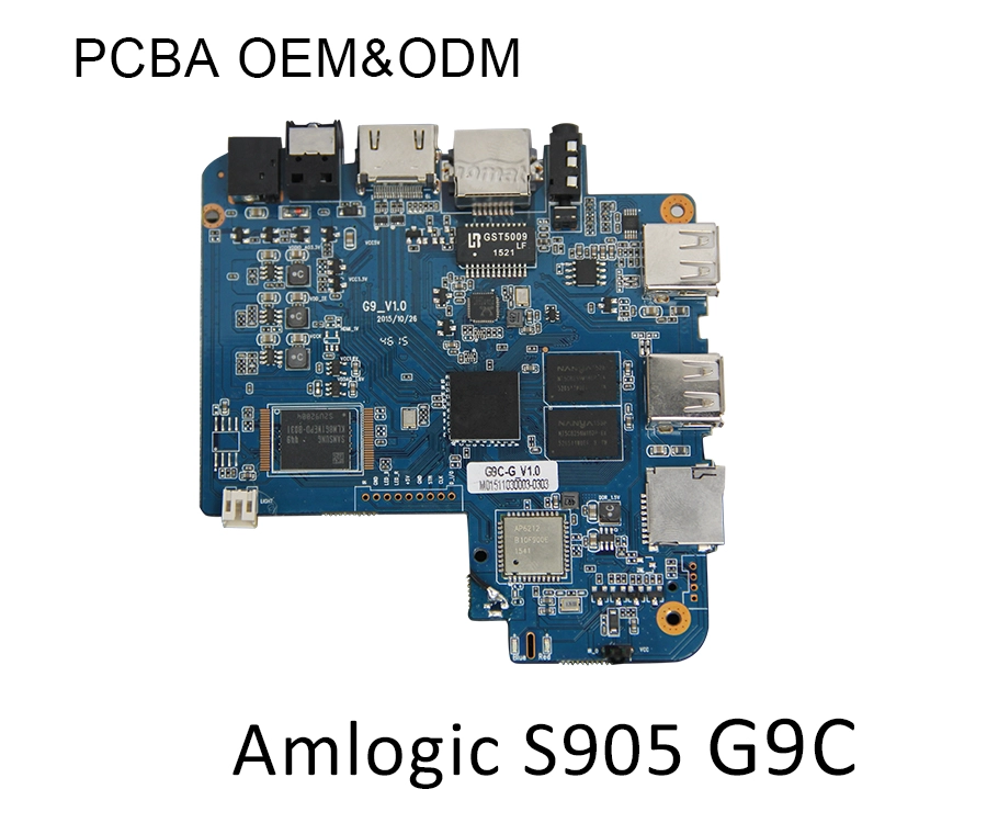
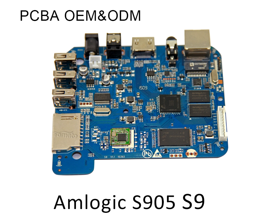
[PoE Setup]        --> Managed PoE+ Switch =================> Custom TV Box PCBA
(Single RJ45 Cable)
Integrating a professional TV Box via Power over Ethernet (PoE/PoE+) streamlines field deployment by combining power and gigabit network data into a single RJ45 cable run:
1
Select and Verify the Network Infrastructure
Required: 802.3at PoE+
1.Select and Verify the Network Infrastructure:Required: 802.3at PoE+。
Ensure the central network switches supply adequate power profiles. Standard 802.3af PoE maxes out at 15.4W, whereas 802.3at PoE+ provides up to 30W, which is necessary to prevent hardware instability when a TV Box drives external USB peripherals or high-bitrate video decoding blocks.
2
Interface the RJ45 Drop to the Hardware Terminal
Physical Installation
2.Interface the RJ45 Drop to the Hardware Terminal:Physical Installation。
Connect the category cable (Cat6 or higher recommended for long runs) from the PoE+ switch panel directly into the isolated PoE module input on the custom TV Box enclosure.
3
Configure Isolated Power Routing
Internal Circuit Step
3.Configure Isolated Power Routing:Internal Circuit Step。
The internal transformer splits the 48V network voltage down to a stable 5V or 12V DC line directly on the Printed Circuit Board Assembly (PCBA), bypassing the standard DC barrel jack while simultaneously lighting up the internal Ethernet physical layer (PHY).
4
Validate Network Link and Thermal Equilibrium
Testing Phase
4.Validate Network Link and Thermal Equilibrium:Testing Phase。
Verify that the link speed negotiates at 1000Mbps (Gigabit). Monitor the integrated circuit temperatures during initial boot to ensure the internal PoE transformer does not exceed thermal thresholds under active hardware decoding workloads.
3. Peripheral and Panel Integration via Industrial Ports
Connecting a commercial media player often involves managing peripheral components like touchscreen overlays, external telemetry sensors, or legacy display panels. Standard consumer streaming hardware lack the required interfaces for these configurations.
| Interface Port | Mechanical Specification | Enterprise Application |
|---|---|---|
| RS-232 Serial | DB9 or 3.5mm TRRS Connection | Enables hardware-level display control, allowing the TV Box to send direct HEX commands to power panels on/off, switch inputs, or adjust backlight brightness without using erratic infrared (IR) blasters. |
| USB 3.0 / Type-C | Native Bus, 5Gbps Bandwidth | Connects high-bandwidth peripherals like interactive touch screens, USB webcams for face detection, or external storage arrays. |
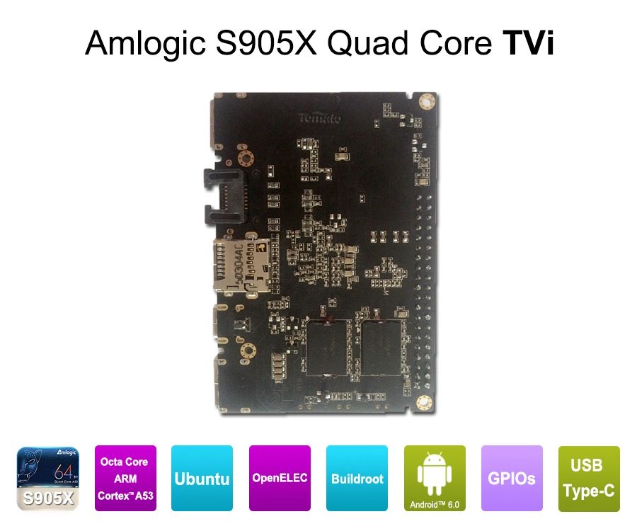
| GPIO Pinheaders | 4-Pin / 8-Pin Programmable Lines | Allows direct hardware communication with physical buttons, motion triggers, or environmental sensors in kiosk enclosures. |
4. Scaled Provisioning: Automated Firmware Provisioning
Connecting the physical cables is only half the installation challenge; provisioning the software across hundreds of devices manually creates a significant operational bottleneck. System integrators require automated configuration protocols upon initial network connection.
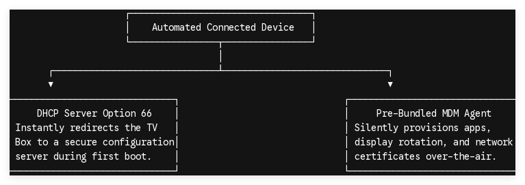
Using customized firmware images built for specific deployment scales allows a TV Box to automatically pull configuration files, cache media assets, and lock down user permissions immediately after the hardware installer connects the network cable.
Technical OEM/ODM Integration Partnerships
Connecting a commercial TV Box demands specialized hardware features and deep firmware flexibility that standard consumer retail players cannot offer. If your current deployment workflow involves unmanaged HDMI connections, messy power supplies, or tedious manual app installations, you need enterprise-grade hardware.
Our engineering team designs custom PCBA configurations with integrated PoE modules, true RS-232 display control lines, and tailor-made Android firmware built for automated network provisioning.
Contact our Senior Engineering and Architecture Team today to discuss your project specifications and secure an evaluation sample built for your commercial workload.
